Showing posts with label Technology. Show all posts

Wednesday, September 25, 2019

Aitendo kits

One of the things I usually do when I go to Akihabara is to visit the Aitendo electronics store. Aitendo store kits are very reasonably priced and there is a great variety. Note that I have already talked about other kits in the past, check the FM microphone and Achandeino. In this post, I wanted to introduce two new kits that I bought and I liked them.


The first kit is a hearing aid circuit (補聴器キット Hochōki kit).


As you probably guessed, the circuit captures sounds through a microphone and amplifies them with a transistor. The user with hearing problems listens to them through headphones.


The second kit is a Tesla coil plasma speaker (テスラ電光音発生器 Tesura denkō-on hassei-ki). By the way, there are now other Tesla kits with larger coils.


This circuit is somewhat more complicated to explain. Basically, it is a high-frequency oscillator that accumulates energy in the coil. The oscillator wave is amplitude modulated by another input wave, for example, music. Bringing a screwdriver to one end of the coil produces an electric arc discharge and makes noise. That noise when modulated by the song turns the coil into a speaker.


It is best to see it with your own eyes. Watch the video I recorded.


You can also use the kit to light a fluorescent lamp.

Friday, February 22, 2019

Electric street light switch

When I walk on the street, I often try to spot devices that make our lives easier without us knowing. If I stop for a second and look around, I usually found myself surrounded by a lot of stuff that I don't always understand or pay attention to.


For example, I found this weird looking device inside a cabinet on the street. I took a picture of it to look it up on the internet later. It turns out that this is an electric street lamp switch (called EE switch by Panasonic). In other words, a device that automatically regulates the current that goes through a street light based on the ambient light.

Thursday, February 7, 2019

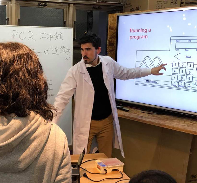
DNA fingerprinting at Bioclub

Last month, I co-organized a DNA fingerprinting workshop at Bioclub, Shibuya. The workshop consisted of a pre-orientation session on Tuesday and 2 days of wet lab experiments during the weekend.


We had a total of 5 attendants, and it was quite challenging to coordinate all of them to complete the workshop in time. Fortunately, the students were all extremely nice and never had a problem with them.


I spent quite a lot of time creating the slides of the pre-orientation session. You can see them above if you want to know the details of the workshop. On Saturday, we extracted DNA from pig and cow liver and amplified a region of the mitochondrial DNA called Cytochrome B by using PCR. Then we mixed the PCR product with a solution of taq1 restriction enzyme and let it digest overnight. On Sunday, we conducted a gel electrophoresis to identify the length of DNA fragments that remained after the digestion. The pattern observed allowed us to distinguish pig tissues from cow tissues.

Thursday, January 17, 2019

Open Source Conference Tokyo Fall 2018

I forgot to report on Open Source Conference (OSC) Tokyo/Fall 2018. This is probably about the 8th time I attend OSC, but I have only reported it a couple of times. The next one will be in February!


As usual, the event was held at Meisei University, about 15 minutes walk from the Tama Zoo and its station. Actually, I'm embarrassed to say that I have never visited the zoo. Maybe I'll do next time.


The talks. You can find them listed on the event website both for the 27th and 28th sessions. The first talk I went to was given by ftake, and it was useful to catch up with  Btrfs and its transactional updates. I also attended a talk about project Sebastien (android sample).


Apart from the talks, the booths were impressive as usual. In particular, I got interested in Musashino's which was full of second-hand routers modified to run OpenWRT. Some keywords I annotated while I was checking out the booths:

Conclusions: going to OSC is always a good learning experience. I got interested in hacking some second-hand router. I also found super cool the telescope made by @nanbuwks, and I was impressed by Murachue's Linux porting to the Nintendo64.


Saturday, November 3, 2018

Google Cloud Next in Tokyo 2018

Last month I took a day off from work to attend Google Cloud Next 2018 in Tokyo. Artificial intelligence and cloud computing are two topics that I love, and this event was great to catch up with the latest developments.


The event was divided into two physically separated areas: one for developers and another one for business. I only attended the former. The stages were pleasantly illuminated, and in general, everything was well organized.


There were numerous technical sessions during the event. Thankfully, Google released an Android application that made it easy to reserve a seat and receive notifications in real-time. Talks were videotaped and published a few weeks ago on Google Cloud Japan's Youtube channel (see the sessions playlist). Unfortunately for non-japanese speakers, the videos are all dubbed into Japanese, and there is no option to select the original audio track :(


Apart from the sessions, there was a spacious booth area for attendants to learn about Google Cloud services through demos (e.g., JapanTaxi's demo) and example architectures (e.g., architectures for game backends).


The next day, I attended another event, organized by GCPUG (Google Cloud Platform User Group) Yokohama, that hosted 2 great presentations by Mete Atamel (Dialogflow) and Felipe Hoffa (BigQuery).

Conclusions: Google Cloud Next was exciting, and I learned a lot about cloud architectures and recent developments in machine learning services such as BigQuery ML. Check out other reviews here and here.

Monday, October 15, 2018

Techbookfest 5

This is the second time I attend a Techbookfest (技術書典) event, and I have to say that I loved both of them. Techbookfest events are events with booths where software and hardware fans can sell their own publications.


The events are quite popular. During the first few hours, you can expect a long queue of people ready to buy their favourite publications before they get sold out. The first event I attended was Techbookfest 2 and it was held in Akihabara. I remember having to wait for a couple of hours in the rain. Techbookfest 5 was held in Ikebukuro. There was a long queue as well but at least it was sheltered.


There were many interesting circles (a person or group of persons in charge of a booth) in Techbookfest 5. Personally, I bought a publication related to a 3D modeling software I have been learning for a while called MagicaVoxel. It seems that the author has also published a book on Kindle called 3D dot modelling (3Dドットモデリング) and has its own voxel webpage. I also bought a publication about creating your own cartridges for the old Game Boy by Nicolli. There was also a similar circle specialized on the Game Boy advance (GBA). I also got a publication related to GAN (Generative Adversarial Network) whose author used to convert a ramen picture into a curry rice one. Finally, I bought another publication about modeling and 3D printing a robot that was then imported into ROS.

Conclusions: Techbookfest is a really nice event if you like software or hardware technical stuff. I hope I can participate as a book writer in the future. I was happy to see that many booths offered their publications in digital format, for example through taimen or booth.

Sunday, September 30, 2018

Tokyo Game Show 2018

My first game console was a Chinese imitation of Nintendo's famikon, called Nipondo. My second one (actually my sister's) was a Nintendo 64. I loved Super Mario 64, Diddy kong racing, Wave race 64 and many others. My third console was a PSP. I enjoyed playing Ridge racer and Daxter on it. And that was it. After that, for a period of more than 10 years I haven't played any game.


I thought I wanted to catch up with that, so I visited the Tokyo Game Show 2018. The exhibition was held in the Makuhari Messe, in Chiba (not Tokyo!), and concentrated a number of big game makers and indie studios as well. According to this report, there were around 107,310 attendants the day I went, on Saturday September 22nd, which was open to the general public.


The exhibition was divided into several halls, and there was a very useful map at the entrance that indicated the location of each exhibitor. The largest game makers had amazing booths with quality lightning, multiple events, and even television coverage. There were also many cute models promoting the games and getting the attraction of all cameras.


However, I preferred the booths of smaller game studios because it was easier to see their games without all the bells and whistles. In particular, I loved the indie games section in the international hall.


One of the most popular platforms was the computer (e.g.: Steam, browser and Windows games). I had never used Steam before, but right after the event I opened an account. The other main popular platforms were mobile (206 titles for Android were exhibited); Nintendo switch, which has the most interesting games for my taste; and the PS4.

Conclusions: participating in this event was a good experience. There was a total of 668 exhibitors and 298,690 visitors. There was so much to see that I probably missed many interesting spots. Here is a complete list of exhibitors, the games they released, their genre, and the platforms they support. Next, I am planning to explore Steam and I would love to try some games on the Nintendo Switch.

Saturday, July 7, 2018

Disassembling a Bluetooth speaker

As you may have noticed from my previous post, I am a fan of disassembling devices with the purpose of learning.


I got this nice Bluetooth speaker as a present from Redhat during a conference in Japan. It works by pairing your phone with the Bluetooth speaker to play music. The speaker provides three push buttons (volume down, play, volume up), a USB interface to charge the battery, a power on switch and a microphone.


The speaker's body is made of ABS plastic and covered by a rubbery silicone wrapper with a nice matte finish. The wrapper has a suction cup to stick the speaker to a surface. Let's look inside.


The body is held together with screws. The speaker and the microphone are glued to the top part. The printed board has pads for an extra microphone and LEDs. I suppose they left them there to customize the final product depending on the price. Finally, the lithium battery is glued to the bottom part.


The speaker is connected to the chip at the lower side of the board, an LTK8002D audio amplifier made by LTKCHIP TECHNOLOGY (ShenZhen). The brains of the Bluetooth speaker are implemented using the AC1533D83234, an SoC (System on chip) made by ZhuHai JieLi Technology (Zhuhai City). From what I could see by inspecting datasheets of similar chips, it (probably) contains a 32bit RISC CPU, GPIO pins, PWM, ADC, DAC and Bluetooth capabilities.

Conclusions: the way the Bluetooth speaker works is quite easy to understand. First, the SoC gets its power from the battery through a voltage rectifier (on the top side). The SoC also uses an external oscillator circuit to generate its own clock signals. The 3 buttons (and LEDs) are connected to the GPIO pins. When the switch is on and we press the play button, the SoC will receive audio data from our phone through the Bluetooth antenna which is printed onboard. Then, the SoC will convert these audio data into an analog signal, adjusting it to the current volume level. Finally, the SoC will forward the signal to the speaker through an audio amplifier. The most interesting part from disassembling this device has been finding and reading the website of ZhuHai JieLi Technology (thanks to Google translate!). I didn't even know this company existed. I wonder how many more companies and chips from China are left for me to discover.

Sunday, July 30, 2017

Debugging the FMP RTOS on QEMU

A few weeks ago I participated in the 7th edition of Tokyo's self-made OS meetup (自作OSもくもく会). This event was held at Cybozu offices in Nihonbashi which are quite colourful and have great views.


During the event there were lots of presentations that touched topics such as file systems, UEFI, kernel page handling, or memory allocation algorithms. I also gave a talk on how to debug the TOPPERS FMP real-time operating system on QEMU.

Monday, July 17, 2017

Blinking an LED with a simple PIC microcontroller

There are many different PIC microcontrollers. Some of them are powerful enough to be used with an arduino-like framework (pinguino) and others are much more constrained. For the former, I suggest using this PIC18F2553 I/SO evaluation board. For the latter, I suggest using a PIC12F675 I/P (or a reference kit). Despite being small and cheap, the PIC12F675 can be powerful enough for many simple applications. Let's take a look at its specs:
  • 10-bit A/D converter (4 channels)
  • 6 GPIO pins
  • Timers
  • Analog comparator
  • Memory (ROM: 1K words, RAM: 64B, EEPROM: 128B)
To compile code for the PIC12F675 you need to install the MPLAB-X IDE and the free edition of the MPLAB XC8 (PIC12F675 is an 8-bit microcontroller) compiler.


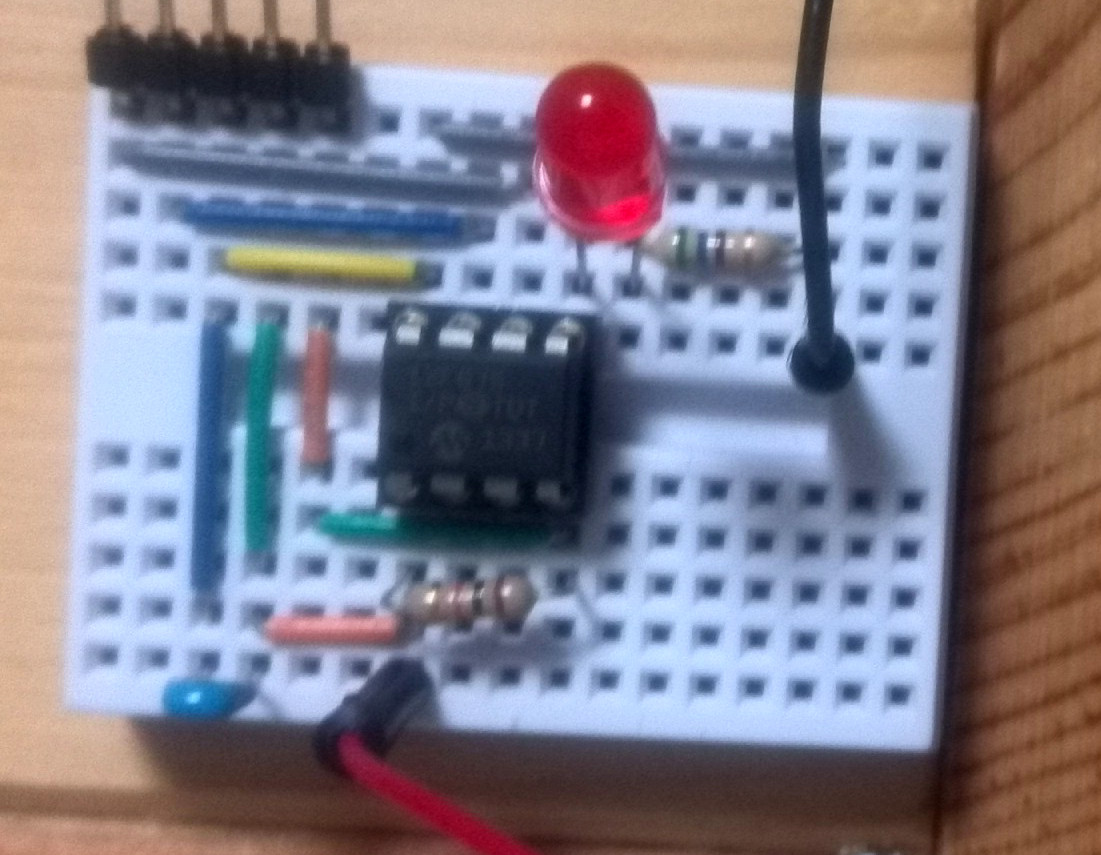
Then, prepare a circuit like the one in the picture on a breadboard. The PIC12F675 contains an internal oscillator so you don't need to supply one. Here we are just connecting the GP2 pin to an LED with a resistor. Additionally, we connect VPP to VDD through a 10kohm resistor and VDD to VSS (ground) with a 0.1uF for programming the chip with Pickit3.


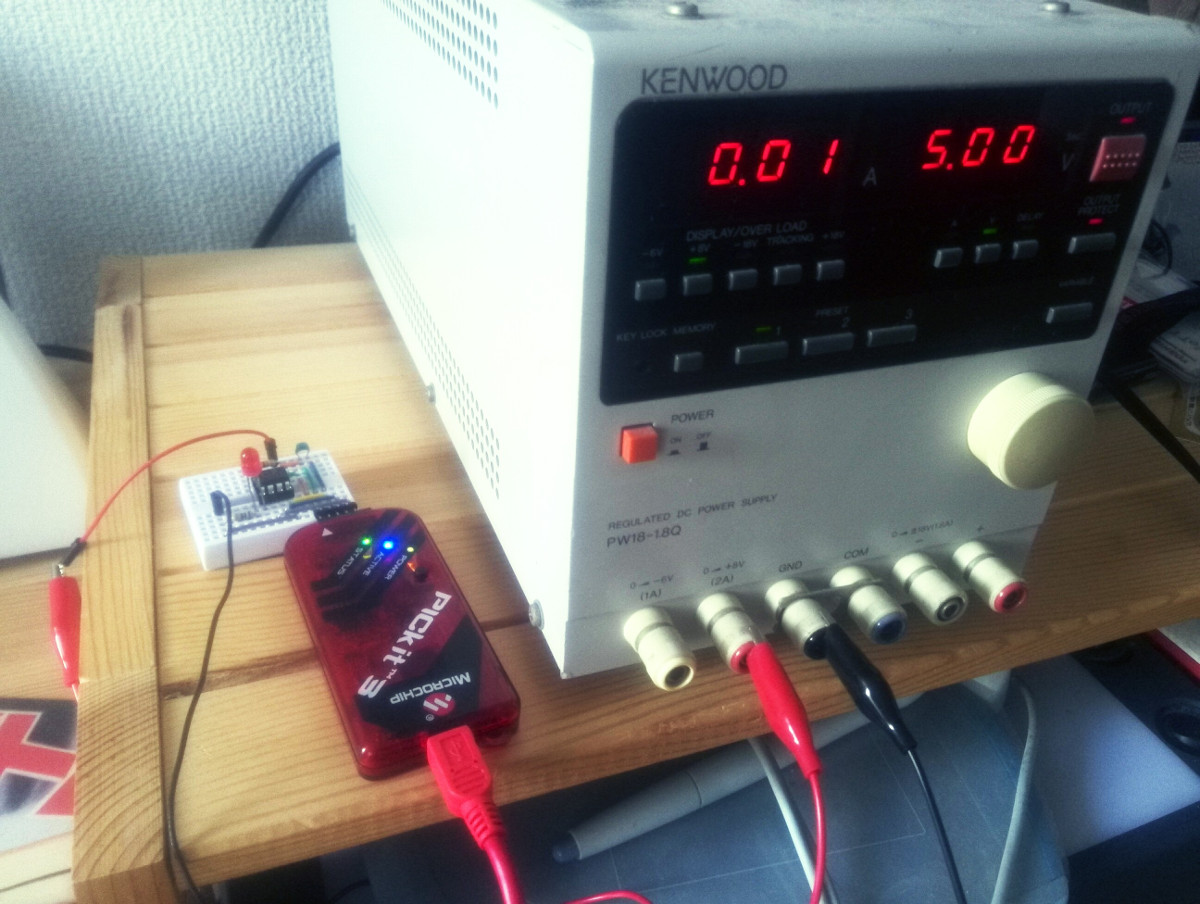
Build the example source code provided by Paolo Rognoni with the MPLAB-X IDE. Connect the board to a 5V power supply and program it with a Pickit3.

Important: if you just bought the Pickit3 and get a "Connection failed" error and a RED status LED, the firmware in your Pickit3 may need an update. In that case, download the Pickit3 programmer application (I had to use v3.10) and open it with the Pickit3 unplugged. Plug it in and click Tools > Check communication. Hopefully it will be connected. Next, click on Tools > Download Pickit operating system, and choose 'hex' to write onto pickit3. Then, click on Tools > Revert to MPLAB Mode and exit the application (if it says no permissions for writing, change the folder permissions to writable). Finally, start MPLAB IPE program (already installed with MPLAB X), click "Connect" and it will update the firmware for you.

Sunday, July 2, 2017

Writing an oscilloscope frontend with PyQT

In previous posts, I talked about two DIY oscilloscopes that I had built (not dessigned): one based on Arduino and another one based on a dsPIC controller.


Although building my own DIY oscilloscope was fun, I had always wanted to get a real one. A few months ago I decided to buy a used one on Yahoo auctions. In particular, it was an Iwatsu BRINGO DS8812 digital oscilloscope (DSO).


Although there were good oscilloscopes for lower prices, the DS8812 fitted all my requirements:
  • Cheap (10,000yen, about 78 euro).
  • Small size, because my workspace was getting full of devices.
  • Enough bandwidth, channels, sampling rate and memory length.
    • DC~100MHz, 2 Channels, 500MS/s, 100kword/channel
  • A remote control protocol (through RS-232C) that was documented.

The only problem that this oscilloscope had, and the reason for its low price, was that the right menu was hard to see. I tried disassembling the oscilloscope and touching different connections but I wasn't able to improve it. For that reason, I decided to create a GUI interface to control and visualize the oscilloscope remotely through the RS-232C interface.


In order to control the oscilloscope, a cross serial cable was required. In my case, I already had a straight serial cable so I only had to buy a null-modem converter which worked great.

 $ picocom -c --omap crlf -b 115200 -f h /dev/ttyUSB0
    --omap crcrlf: outputs CR/LF instead CR (set osc to CR/LF delimiter)
    -h: enables RTS/CTS
    -c: local echo 

The most tricky part was passing the appropriate parameters to the serial terminal. Picocom is my favourite serial terminal, and these are the parameters I used.


With that in place, I finally managed to get a response from the oscilloscope using the command "DATE?" (commands that end with a question mark represent requests to the oscilloscope).


I programmed the frontend using PyQT (Python bindings for the QT GUI library). I found the QT designer to be particularly easy to use and robust. The source code is on my github account and it uses pyserial for communicating with the oscilloscope, and matplot for displaying waveforms.


Here is a snapshot of two square waveforms on each channel. The app is not very sophisticated but it does its job and can be easily extended in case I need more functionality.


For example, here I implemented an FFT view of the acquire waveforms. This was a paid functionality on the original oscilloscope.

Conclusions: I'm glad that I got a oscilloscope that I could controll remotely. Now I can easily store waveform data, analyze it or save it as an image file. I really enjoyed working with PyQT and the QT designer. They are very powerful and easy to use. Last but not least, I summarized my "endeavour" in a few slides and presented this project at OSunC in Kawagoe.

Saturday, May 20, 2017

OSC 2017 Spring

The Japanese Open Source Conference, usually known by its initials OSC in Japan, is a great event for open source enthusiasts. It is celebrated in different japanese cities and regions throughout the year such as Tokyo, Hamanako, Osaka, Hiroshima, Fukuoka, Kyoto, Nagoya, and many more. Here is their official OSC Twitter account.


Although I have attended the conference many times I had only reported once in 2013. This time I attended Tokyo OSC 2017 Spring which was held at Meisei University, a private University that has great rooms with multiple screens.


During the conference I made a short introduction to Fuego, an open source test framework that I'm contributing to recently. You can find the slides here. This wasn't my first presentation in OSC but it was the first one I did as part of my job. You can also find the videos and slides of other presentations given during the conference here. I was very interested in the Lagopus project, which supports DPDK (a cool framework for zero-copy network applications); the Vuls vulnerability scanner; and also Volumio, a Hi-Fi digital music Linux distro.


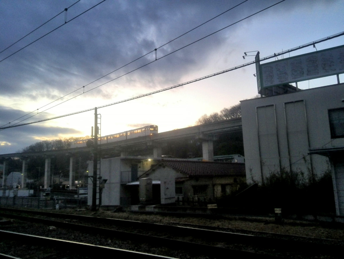
Although I normally use the Tama Dōbutsuen Station which is right in front of a zoo (Dōbutsuen means zoo), about 15 min walk to the OSC building, most people prefer to use the Chuo Daigaku-Meisei Daigaku Station on the Tama Monorail. Here is a picture of it on my way back to the station.

Conclusions: it's always fun to attend the OSC and learn about new trends, software and make new friends. Also I think it is especially fun if you make your own presentation.

Wednesday, May 17, 2017

Assembling a dsPIC-based DIY oscilloscope

In August 2015, I attended a Tokyo Hackerspace event called building a DIY oscilloscope. However, it wasn't until December 2016 that I finally assembled and tested it!.


During the event, we received a kit from Carl Blaksley that was based on an original design by Ajoy Raman. The hardware is quite simple and consists of 3 main components: the analogue interface, the processor and the USB interface. The analogue interface includes a few RC filters and 2 programmable gain amplifiers (SPI protocol) MCP6S22 (one for each channel). The amplified signal is then sampled by the processor, a dsPIC30F2020 which contains a 10-bit 2 Msps ADC (shared among the channels enabled). Finally, the USB interface is handled by the famous USB-serial FT232RL chip. Carl was nice and sent me the Kicad design files of the board. The assembly went quite smoothly but as always I had to debug a hardware problem that ended up being caused by my USB (a cross USB cable was needed).


The software was written in python and worked fine on Ubuntu 16.04 (there is also a visual basic version for Windows). To test it, I installed this amazing Android function generator application and connected it to the oscilloscope through a 100yen (sold at Seria) headphones stereo amplifier.

Saturday, April 8, 2017

Converting inches to centimeters in your head

While reading a book from the USA about woodworking, I felt the need to find an easy way to roughly convert inches to centimeters quickly in my head. As you probably know 1 inch equals 2.54cm. The problem is that it's not easy, at least for mortals like me, to quickly multiply by 2.54 mentally.


So after a few minutes I came up with this formula:
 cm = in*2 + round_down_to_even(in)/2 + 1
For example, let's suppose that we want to convert 13 inches to centimeters in our head. We apply the formula above and we get:
 13*2 + round_down_to_even(13)/2 + 1 = 26 + 12/2 + 1 = 33cm
While the exact value is 33.02 cm, we got pretty close. I found that this formula works reasonably well for the first 50 inches (127cm) where the error averages to about 0.56cm (see the figure). Unfortunately, the accuracy of this formula decreases proportionally to the number of inches. I link here a LibreOffice spreadsheet that I used to calculate the normal distribution for this formula (see the columns aprox2) and compare the results with other similar formulas that I thought up. If you know of formulas that beat up mine, I'd be glad to know them. Please write a comment.

Thursday, December 8, 2016

How to run the LTspice circuit simulator on Linux

I often use LTspice for simulating my circuits or even organizing workshops. Unfortunately, LTspice is distributed as a Windows application. In this post, I'll explain you how to run LTspice on your Linux distribution using WineHQ.
 $ sudo dpkg --add-architecture i386   
 $ sudo add-apt-repository ppa:wine/wine-builds  
 $ ls /etc/apt/sources.list.d/  
   wine-wine-builds-trusty.list  
 $ sudo apt-get update  
 $ sudo apt-get install --install-recommends winehq-devel  
 $ mkdir WINE  
 $ echo "export WINEPREFIX=$HOME/WINE" >> $HOME/.bashrc  
 $ source $HOME/.bashrc  
First, you need to install Winehq using the instructions for your Linux distribution. The instructions above are for Ubuntu LTS 14.04 Trusty (64 bit). The folder WINE represents the Windows filesystem hierarchy (e.g. WINE/drive_c/ represents the C:/ folder in Windows).
 $ wine64 LTspiceXVII.exe  
Then, download LTspice from Linear Technology's homepage and execute the binary with wine64. Here I'm using the latest version XVII, but you can also install the version IV without problems.
 Menu > Wine > LTspiceXVII  
After the installation is complete you can use LTspice as in Windows. You can launch LTspice from the menu or from the generated Desktop icon. During the installation and execution of LTspice, WineHQ may need to download extra dependencies. Just click on yes and everything should go smoothly. If you are new to LTspice check out these slides and videos.

Thursday, December 1, 2016

Making your own PCB with the toner transfer technique

This is something that I had wanted to do for a very long time. There are several methods for making your own PCB. Out of them photolithography will probably give you the best results. However, toner transfer is one of the easiest and cheapest.


For my first toner transfer PCB, I used a Kicad project (a transistor checker) from the great Japanese electronics magazine Transistor Gijutsu (lit. transistor technology). I opened the project on Kicad with pcbnew and printed the B.Cu (Backside copper) layer on a photo paper (the one in the picture is popular among Japanese hobbyists) using a laser printer. Reflecting back, I should have also printed the drill holes (just mark the "real drill" checkbox when you print the B.Cu layer) and add a copper-pour ground plane to save Ferric Chloride. Then, using an iron at the lowest possible temperature I transferred the footprint from the paper to a copper board. You have to be patient here (it took me 12 minutes) and apply enough pressure.


Next, put the board in hot water and remove the paper slowly with your fingers. Don't worry about the ink, it won't come off from the copper plate.


Clean deeply using a multipurpose or window cleaner.


Check the tracks carefully. If you notice that some tracks are not completely black cover them with a water-resistant pen. In this case I used a very strong pen especially made for PCBs. However, I would recommend using a normal one because this one was too strong and it was hard to remove it later.


You can easily cut your copper plate with a P-cutter tool.


Next put some Ferric Chloride into a zip bag together with your board, and swing it slowly inside a bucket with hot water (makes the reaction faster). Make sure you always wear rubber gloves and goggles when you handle Ferric Chloride because it's a very dangerous material. You will see how the exposed copper is slowly consumed by the Ferric Chloride. Once the copper is gone take the board out of the bag. Don't leave it for too long or the Ferric Chloride will attack your tracks from both sides.


This is the result. Notice how the tracks are still covered with the ink from the laser printer which prevented the Ferric Chloride from reacting with the copper.


Now take that ink off with acetone or a nail polish remover.


Drill the holes with a hand drill. I am using Tamiya's fine pin vice with a 0.8mm bit from Proxon.


Next solder your components into the board. Here I'm using lead-free solder which requires higher temperatures than lead solder. If your components are fragile or you are not quick enough with your soldering iron use lead solder instead.


Once the board is soldered it's time for testing. A typical multimeter will emit a sound when it finds a short.


If you make a mistake such as connecting a component in the wrong way, you can use desoldering braid or wick. Make sure your soldering iron is at a high enough temperature. Check other desoldering techniques here.


If you are unlucky like me, you may need to debug further your circuit. In my case, I simulated the circuit on LTSpice and found out that there was a mistake in the footprint. I solved it by cutting a track with a normal cutter.


And there you go, the transistor checker board is now working!.


Finally, make sure that you neutralize the PH of the resulting liquid (copper chloride) with sodium carbonate to a value between 7.0 and 8.0 (use a PH testing paper). Then, solidify the solution with cement and dispose of it. Never put it down the drain because the residual copper ions left in the solution can damage your pipes and the environment.